The control elements of the hydraulic synchronization circuit are divided into two types: loop control and closed loop control. Open-loop control components include manifold valve, synchronous motor, synchronous cylinder, etc. The manifold valve is widely used because of its convenient connection, simple structure and low cost.
The manifold valve (also known as the synchronization valve) controls two or more oil cylinders or hydraulic motors in a hydraulic synchronization system to maintain the same speed movement. There will be a speed difference (synchronization error) ≤3% between the two cylinders. When the end point is reached, the lagging cylinder continues to move to eliminate the synchronization error (that is, end point compensation). Usually the diversity flow is equal ratio (i=1:1) called the synchronous valve, and the standard name is the flow dividing and collecting valve. The valve structure is divided into three types:
Fixed synchronous valve (also known as: ordinary synchronous valve). The working flow rate is ±10% of the rated flow rate, which is suitable for the synchronous system with constant flow rate of fixed pump oil supply or oil cylinder. When the flow rate is greater than or equal to 10%, the valve pressure difference increases, and vice versa. At this time, the synchronization error becomes uncertain. Its characteristics are: simple structure, low price and convenient installation.
Adjustable synchronous valve is based on the fixed synchronous valve, the primary orifice is converted into a variable orifice, and the handle is used to adjust the ratio of output and input artificially with reference to the operating conditions of the actuator. The valve is mainly suitable for the synchronous circuit of differential cylinder or fixed-value proportional diversity flow.
Self-adjusting synchronization valve (also known as: automatic adjustment of working flow and error adjustable synchronization valve). The working flow is 3-5 times the minimum working flow to keep the diversity flow synchronization, which is suitable for the synchronous system where the variable pump oil supply or the cylinder speed frequently changes. The valve is equipped with a synchronization error fine-tuning knob to facilitate the user's on-site adjustment. Generally, the adjustment has been completed before leaving the factory, but the user needs to implement the adjustment according to the manual when the user has higher requirements. The valve is a broad-spectrum (fool) type, which can meet the requirements of various working conditions but the cost is relatively high. Currently there are many applications. The self-adjusting synchronous valve basically replaced the adjustable synchronous valve in our company.
In addition, according to specific requirements, our company has derived dual-core synchronization valves, cartridge synchronization valves and three-way synchronization valves.
Dual-core synchronization valve (also known as automatic adjustment of working flow, two-way error adjustable synchronization valve). Its structure is based on the self-adjusting synchronous valve, the primary fixed-difference pressure reducing valve group and the spool are set as two sets of synchronous control systems for splitting and collecting, and the synchronization error adjustment knob is also set with one set for each of the manifolds, so that the synchronous valve The synchronization error is adjusted to achieve unidirectional adjustment of the diversity flow. Structurally, the symptom of the synchronization error crossover of the synchronization valve (that is, the inconsistency between the shunt synchronization error and the collection synchronization error) is solved. Its characteristic is that it can adjust and use the difference of the diversity stream in a targeted manner, which is suitable for customers who have requirements for two-way synchronization.
Cartridge synchronization valve is a new type of hydraulic synchronization control element that adapts to cartridge hydraulic components (such as two-way cartridge valves, threaded cartridge valves, etc.). It is characterized by small size and low hydraulic resistance, and is easy to integrate in medium and high-power hydraulic systems. It can also be combined with proportional components and digital components to form a closed-loop hydraulic synchronous control system.
The three-way synchronous valve is a fixed synchronous valve in structure, but it has a small size and beautiful appearance. The pipeline connection is of a "T" type structure, which is similar to a three-way assembly of pipe fittings, which facilitates the user's pipeline layout. It is an ideal product for ordinary users of hydraulic synchronization valves.
Synchronous valves operated by our company are divided into aviation coordination (synchronization) valves and civil synchronous valves. There are two types of synchronization accuracy: ordinary type (synchronization error 3%) and high-precision type (synchronization error 1.5%) for users to choose.
The diversity flow synchronization valve produced by our company enjoys independent intellectual property rights in the structure of synchronization error fine-tuning, additional secondary amplifying mechanism and two-way error adjustable structure. The enterprise standard of the product is practical and avant-garde in the same industry (we participated in the compilation of the national synchronous valve industry standard), so the performance, structure and price are leading.
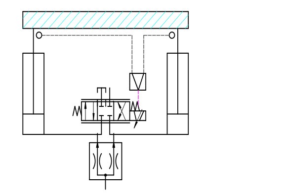 |
Closed loop synchronous system a. As shown in the figure, the synchronizationvalve controls a certain synchronization error.The detection error signal of the displacement or speed sensor is differentially amplified and the electronic control valve discharges the overspeed oil circuit to fine-tune the synchronization error. c. The synchronization error includes the static and dynamic response results, which are specifically based on the value of the transfer function obtained after the electro-hydraulic synthesis is given. d. The primary control function of the synchronous valve is to reduce the diameter specification of the electric control valve and reduce the cost of the system. e. The electro-hydraulic multi-cylinder control adopts a single-cylinder oil supplement or oil drain circuit. |
Lifting or panning synchronization loop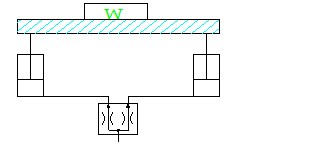 |
Oil inlet synchronization circuit: the synchronization valve is connected to the rodless cavity side of the cylinder. Generally used in lifting and horizontal push synchronization systems. The size of the valve is selected according to the pump or diversity flow. Precautions: |
|
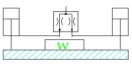
Suspended (negative load) synchronous circuit
|
Synchronous circuit of oil outlet. The synchronization valve is connected to the rod cavity side of the cylinder. Generally used for suspending potential energy load synchronization system. The selection of valve specifications should consider the flow rate of the cylinder after shifting. If the valve is installed on the rodless cavity side, the cylinder with rod cavity must be equipped with a balance circuit to prevent overspeed and loss of control. The precautions are the same as above. In addition, the system synchronization valve with a cylinder gear ratio greater than 2 should not be installed in the rod cavity of the cylinder, otherwise the pressure in the rod cavity will double when the cylinder is extended, which will damage the synchronization valve. |
|
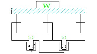
Three cylinder series synchronous loop
|
Series three cylinder synchronous circuit. With a outlet 1:2 and a outlet: 1:1 synchronous valve connected in series into a three-cylinder synchronous loop. For lifting and recumbent systems. The pressure loss and synchronization error in the loop is the sum of the two valves. |
|
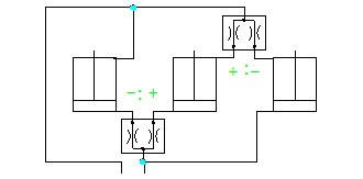
Three cylinders connected with synchronous circuit
|
Parallel three-cylinder synchronous loop. With two equal ratio synchronous valve and connected into a three cylinder synchronous circuit. The size of the rod-cavity synchronous valve is smaller than that of the rod-cavity side valve due to the variable speed ratio of the cylinder. The potential energy load should add a balance loop, and the pressure loss in the loop = (1+1/ I) ΔP (I cylinder speed ratio). Synchronization error is the vector sum of two valves. If the error of the two valves is equal, the synchronization error after the speed and slow collocation =δ+ (-δ) +δ=δ. |
|
Four cylinder series synchronous loop
|
Four cylinder synchronous loop connected in series. Note: |
|
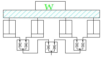
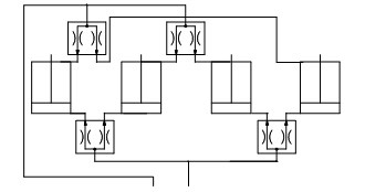
Four cylinders connected with synchronous circuit |
Parallel four cylinder synchronous loop. With four equal ratio synchronous valve speed matching and connection into a synchronous circuit. This is the most efficient connection with a synchronous valve to control each cylinder. The calculation of pressure loss and synchronization error is the same as for the three-cylinder parallel circuit. Note: A. For the cylinder supported platform, it is suggested that the synchronous valve A\B of the lower chamber of the cylinder be connected to the diagonal cylinder port of the platform. B. The cylinder distribution is arranged in A "one" word, the cylinder lower chamber synchronous valve A\B port is symmetrically connected with the two ends of the cylinder port |
|
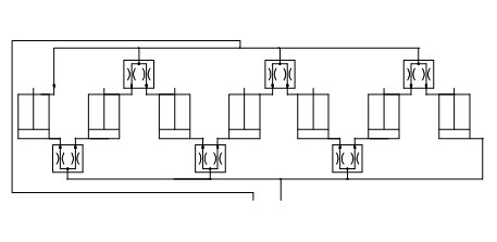
Synchronous valve open-circuit method of multi-cylinder synchronous circuit
|
This connection method is mostly used for multi-cylinder synchronous loop with odd number of cylinders or different cylinder diameters. The characteristic is that each pair of oil cylinder has a synchronous valve control, in the debugging synchronous process is more intuitive and convenient. The overall synchronization error is added up one by one. Note: A. The synchronous control response between the head and tail cylinders is slow, so the two cylinders with variable loads had better be installed in a valve control. B, according to the vector synchronization error of a single synchronous valve for comprehensive matching to obtain the best synchronization effect. |
|
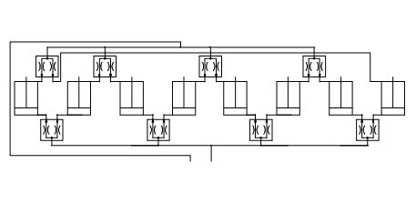
Synchronous valve closed circuit method of multi-cylinder synchronous circuit
|
This connection method can only be used for even number of cylinders of multi-cylinder synchronous loop. It features two valves for each cylinder. So the error is smaller. |
|
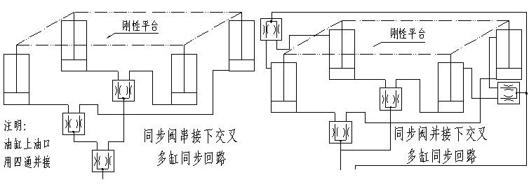
Plane load synchronous valve cross-connected multi-cylinder synchronous circuit
|
The loop uses a platform frame with good stiffness to offset the synchronization error between the two valves. According to the left figure, if the platform stiffness is good enough, only two valves can be used to control the diagonal to complete the synchronization. The circuit is characterized by small error, fast response, small pressure loss and cost saving. |